Task 10
Molding and casting
In this week, I was given a task to have a group assignment and an individual assignment. The group assignment was to review the safety data sheets for each of your molding and casting materials, then make and compare test casts with each of them, and the individual assignment was to design a mold around the stock and tooling that you'll be using, mill it (rough cut + (at least) three-axis finish cut), and use it to cast parts
Introduction
There are number of advantages of Molding and Casting in making different parts. A mold almost takes the same amount of time as 3D printing the object. Once the mold is made, the advantage is we can replicate the part as many times using the same mold with far less time and effort
How does it work?
There are many different ways of molding and casting. Most of the synthetic or plastic products we have around us have probably been cast from a mold, either by injection, insert (forming plastic parts around non plastic parts) vacuum (packaging), blow (like for plastic bottles) and many other techniques.
Group Task
In this week, we focused on flexible or soft mold, which requires creating a flexible mold out silicone by machining a soft material i.e. milled wax. This is the first step and a simpler process since having a flexible mold allows us to remove the cast objects easily. The Guerrilla guide was very useful to get an initial guidance, tips and explanation of the process machining and casting soft molds.
Basically, the process involves CNC milling a positive shape from machinable stock (in our case we are using hard wax because it is recyclable) then casting a silicone (negative) mold from our wax, and then using this to cast our final shape in resin.
Review of Materials and Safety Datasheets
First and foremost, we started with the group assignment; my groupmates were Jobin and Sahan. Before begining anything, our instructor for this week Ari
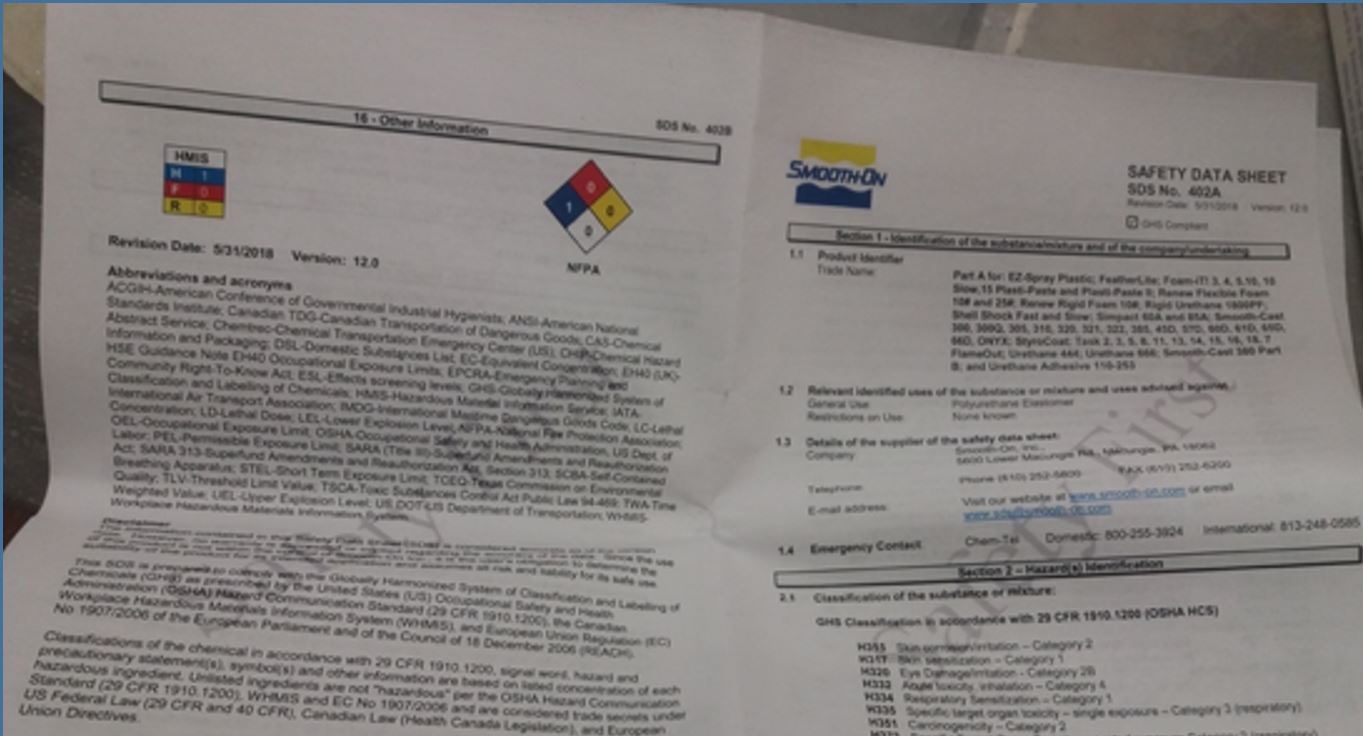
gave us instructions of molding and casting, he presented us the process of creating molds, the available matrials and the safety assoiciated when dealing with these mateials as skin contact with matrials can be allergic and can cause irritation to skin and eyes if
safety guidelines are not followed. It is important to work in a well-ventilated room, to use safety gloves (vinyl gloves only), glasses and a lab coat.
We started reviewing the molding materials in the Lab and their safety datasheets.
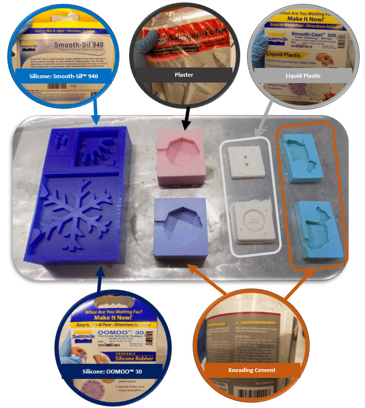
- The below molding materials are avaiable in the laboratory:
- OOMOOTM 30.
- Smooth-SilTM 940.
- Smooth-castTM 300 Series.
- Cement.
- Plaster.
- VytaflexTM Series.
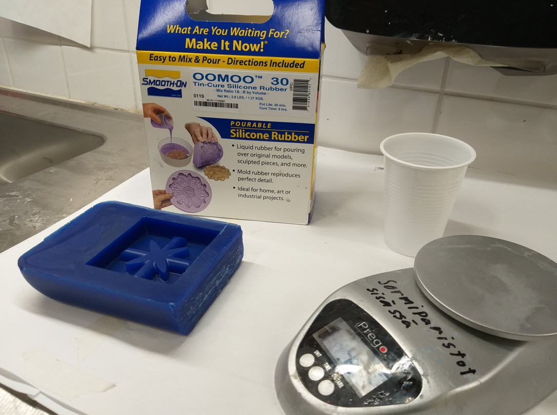
Product Overview: No Vacuuming – No Scale – Easy To Use . . . OOMOO™ 25 & 30 are easy to use tin cure silicone rubber compounds that feature
convenient one-to-one by volume mix ratios (no scale necessary). Both have low viscosities for easy mixing and pouring . . .
vacuum degassing is not necessary. Both products cure at room temperature with negligible shrinkage. OOMOO™ 30 has a
30-minute pot life, with a six-hour cure time. OOMOO™ 25 is a faster version, with a 15-minute pot life and 75 minute cure time.
Safety: Use in a properly ventilated area (“room size” ventilation). Wear safety glasses, long sleeves and rubber gloves to minimize contamination risk. Wear vinyl gloves only. Latex gloves will inhibit the cure of the rubber.
Product Overview: Smooth-Sil™ 936 is a lower viscosity version of Smooth-Sil® 935 platinum silicone rubber (21,000 cps vs. 40,000 cps). It is easier to
mix, vacuum degas and pour. Smooth-Sil™ 945 offers the convenience of a 1A:1B by volume mix ratio and a fast 6 hour cure time. Smooth-Sil™ Platinum Silicones are used for rapid prototyping, wax casting (foundries and candle makers), architectural restoration
and for casting concrete. Smooth-Sil™ 940, 950 and 960 are suitable for food related applications.
Safety: Use in a properly ventilated area (“room size” ventilation). Wear safety glasses, long sleeves and
rubber gloves to minimize contamination risk. Wear vinyl gloves only. Latex gloves will inhibit the cure of the rubber.
Product Overview: The Smooth-Cast™ 300 Series of liquid plastics are ultra-low viscosity casting resins that yield castings that are bright white and
virtually bubble free. Vacuum degassing is not necessary. They offer the convenience of a 1A:1B by volume or 100A:90B by weight
mix ratio. The differences between them are pot life and demold time.
Safety: Wear safety glasses, long sleeves and rubber gloves to minimize contamination risk. Use only in a well-ventilated area.
Product Overview: Cement is a very useful binding material in construction. Its a powdery substance made by calcining lime and clay, mixed with water to form mortar or mixed with sand, gravel, and water to make concrete.
Safety: Wet cement is strongly caustic (pH = 13.5) and can easily cause severe skin burns if not promptly washed off with water. Similarly, dry cement powder in contact with mucous membranes can cause severe eye or respiratory irritation. Wear safety glasses, long sleeves and rubber gloves.
Product Overview: Plaster, a pasty composition (as of lime or gypsum, water, and sand) that hardens on drying and is used for coating walls, ceilings, and partitions.
Safety: The chemical reaction that occurs when plaster is mixed with water is exothermic. When plaster sets, it can reach temperatures of more than 60 °C and, in large volumes, can burn the skin. Donot inhale, it can cause irritation. Wear safety glasses, long sleeves, rubber gloves and masks
Product Overview: Using Smooth-On’s exclusive “V-Polymer™” technology, VytaFlex™ urethane rubbers offer superior physical and
performance properties for casting concrete. VytaFlex™ urethanes are available in 10A, 20A, 30A, 40A, 50A and 60A
Shore hardness’s and feature convenient one-to-one by volume mix ratios
Safety: Wear safety glasses, long sleeves and rubber gloves to minimize contamination risk. Use only in a well-ventilated area.
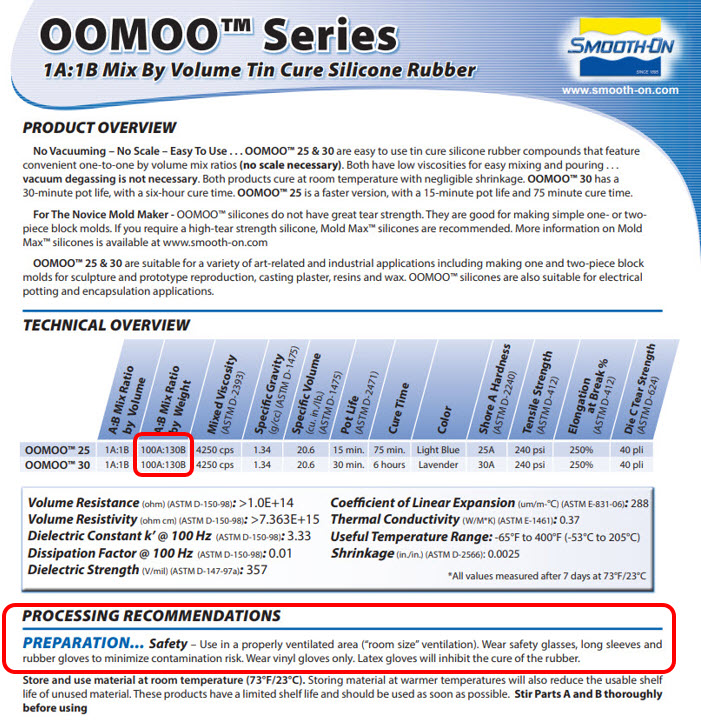
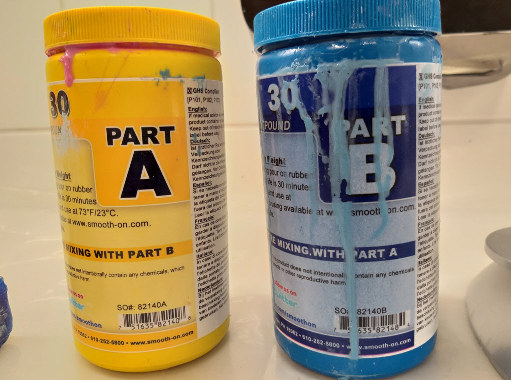
Other than the safety precautions, the most important thing to note is the mix ratio. Each silicone requires a part B catalyst that cures the silicone and needs to be thoroughly mixed together before pouring. As you can see above in the figure, the OOMOOTM 30 requires a 100A:130B mix, which can be calculated on a scale by adding the 130% Part B of the weight of silicone.
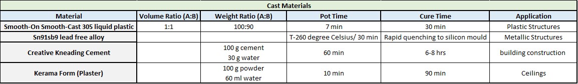
The materials and the processing conditions are described in the table below, which contains the mold materials, volume/weight ratio, mixing time, cure time and the applications related to these materials.

- Equipments required:
- Nitrile Gloves : To minimize skin exposure with the chemicals.
- Safety Glasses : Protection from eye contact.
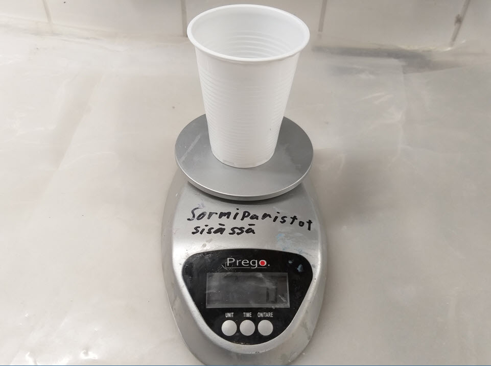
- Weighing machine : Accurate weighing and mixing of the substances.
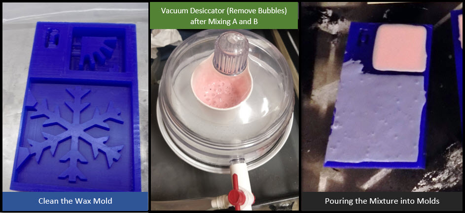
- Vacuum desiccator: De-airing the mixed slurry to release/avoid bubbles during or after curing.
- Wooden sticks : Mixing the slurry substance in the mixing container
- Syringes : Used to fill the cast materials
- Release Agent : To sparay the wax mold with a release agent, It is handy to make the demolding easier
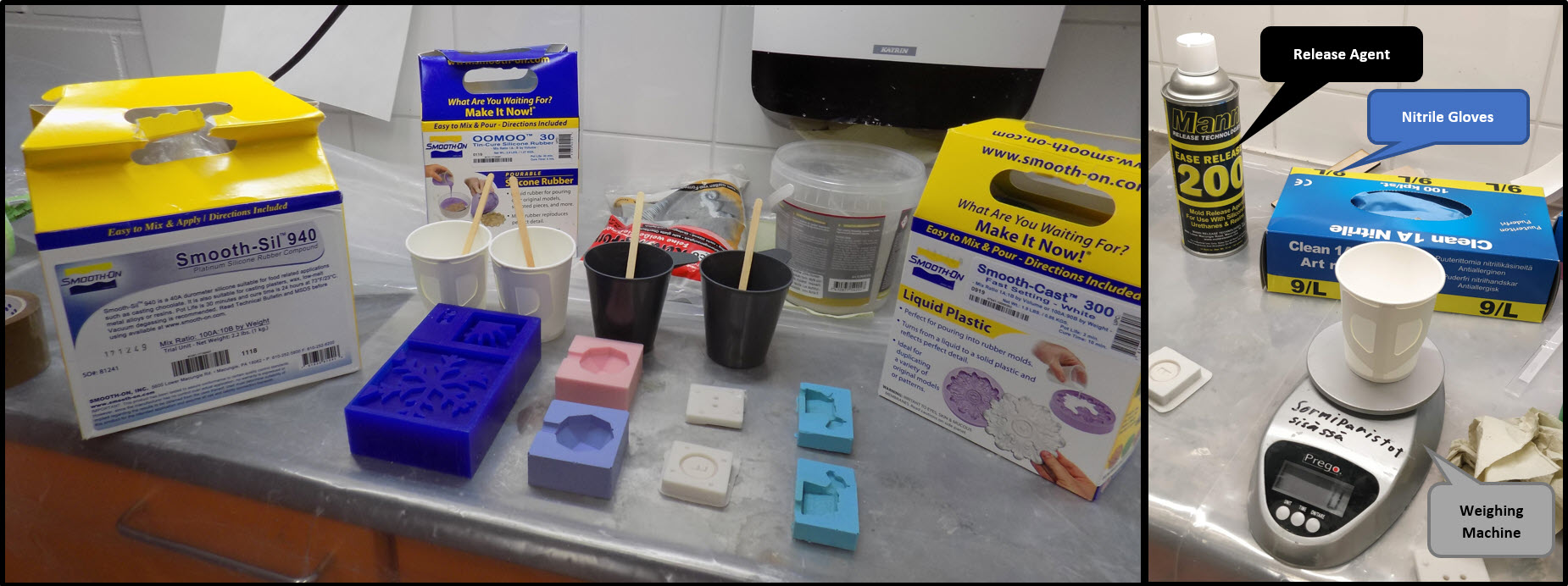
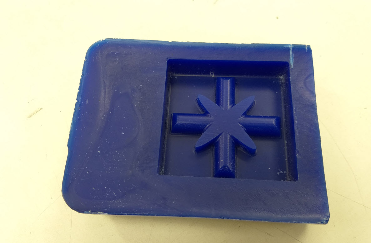
We decided to make use Silicone: Smooth-Sil™ 940 and Silicone: OOMOO™ 30 Silicone Rubber for our mold. For this purpose, we utilized an existing model fabricated by previous year students. For Molding, the vacuum desiccator was being utilized for de airing the bubbles made after through mixing of A and B. Below material and mold were being used for the group work
The Tables in figure 3 and figure 4 were being utilized to perform the mixing ratio of Substance A and B. Clean the wax with a light brush/cloth inorder to remove any dust particles being present in the Wax mold. We started mixing the Smooth-Sil™ 940 and OOMOO™ 30 Silicone, we estimated according to the wax mold the total mixture of A & B required which was about 100 g approximate and referred to figure 3 to find the exact mixing ratio of A and B. Before Pouring the Ma Both materials have a Pot Time of 30min, cure time of 24 min (Smooth-Sil 940) and 6 min (OOMOO 30 Silicone).
Similarly, we started to take the weight of cement and water, Plaster and water, and the Liquid Plastic(Smooth-Cast 300) for A and B. The Tables in Figure 3 and 4 are good reference to look for. Only plaster required the de-aring to reduce the air bubbles. All other materials were free from air bubbles. The cast was kept overnight for curing and in the next day all materials were being cured. Due to broken mold, one of our cement cast was broken. Remaining materials were successfully casted
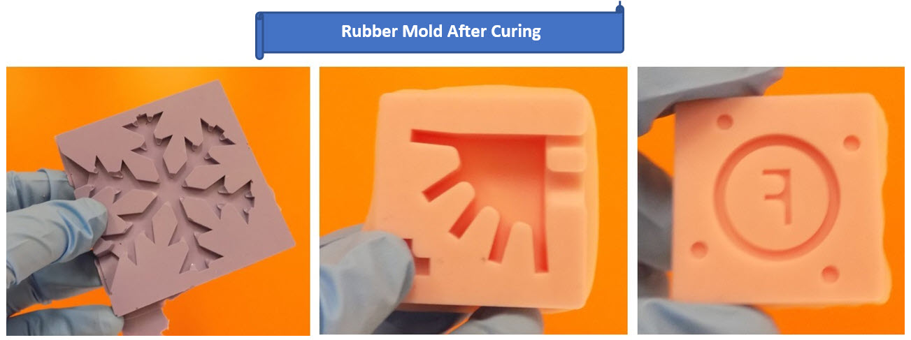
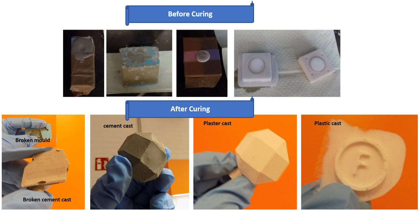
It was being observed that although OOMOO™ 30 mixture was being de-airing throughly, the result after curing was not good as compared to the Smooth-Sil™ 940. The Smooth-Sil™ 940 takes 24 hours but the result is pretty good. Cement and plaster-work well with rubber mold. Due to Limitation of time, I decided to use OOMOO 30 mold for my individual work.
Individual Assignment
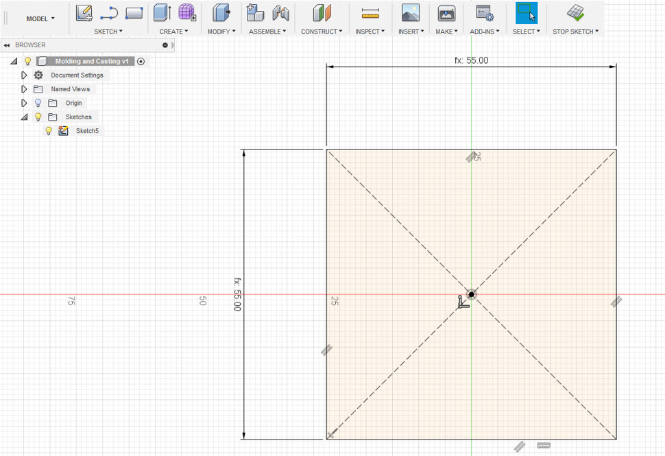
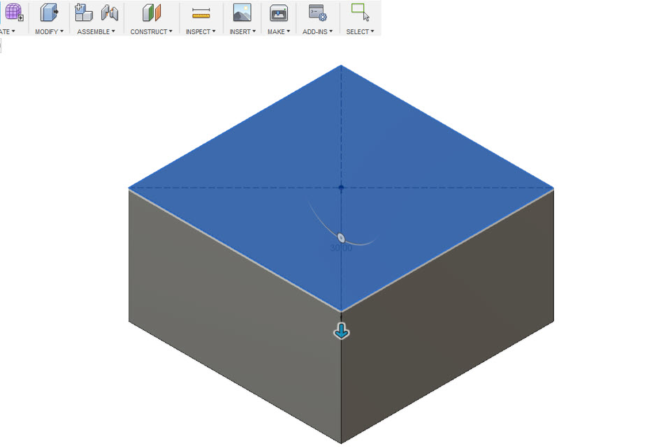
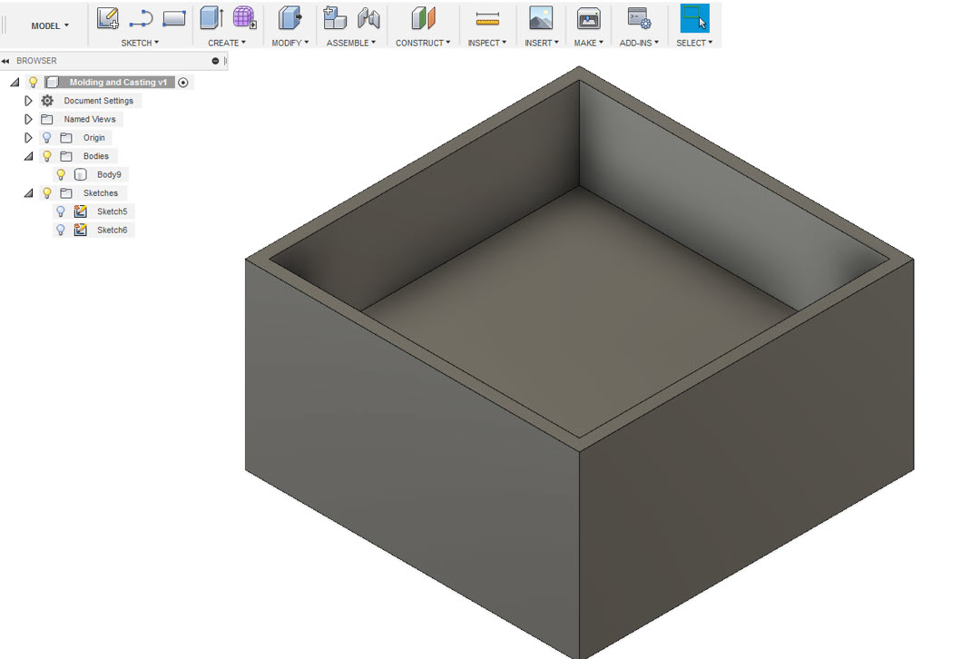
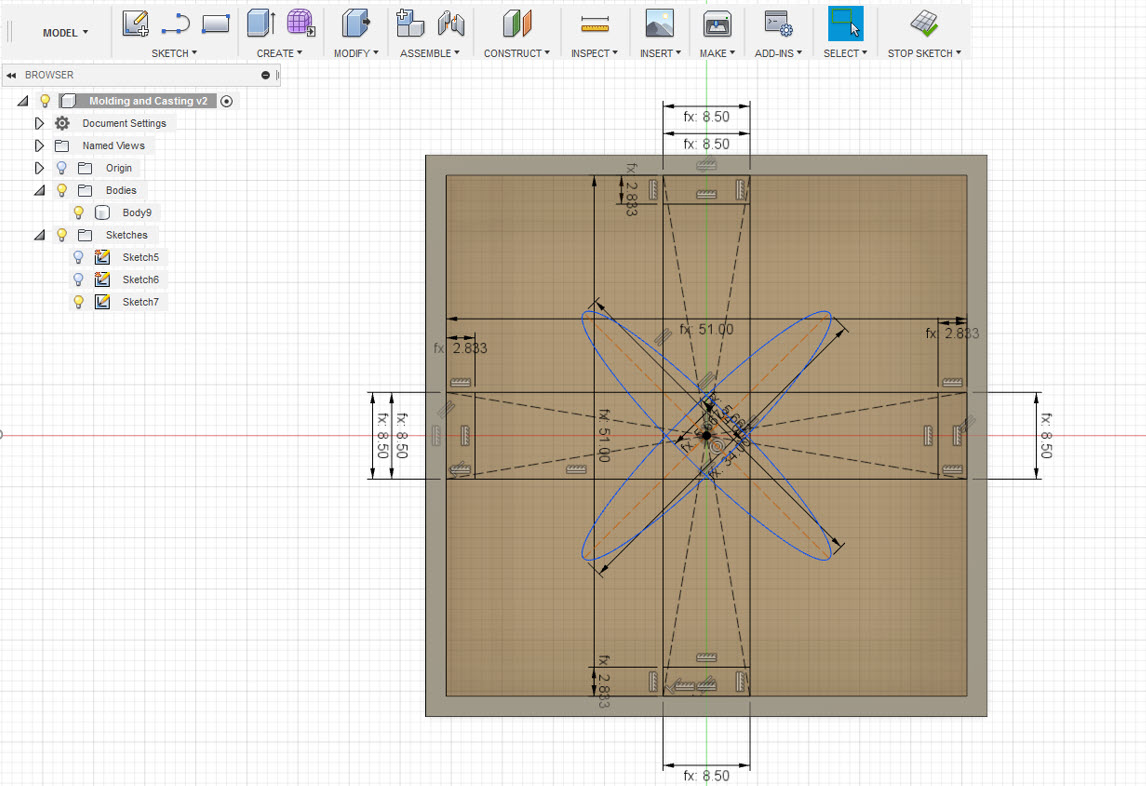
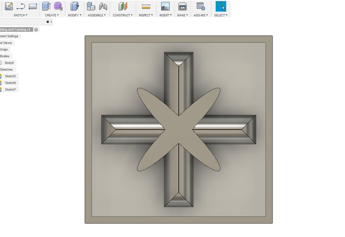
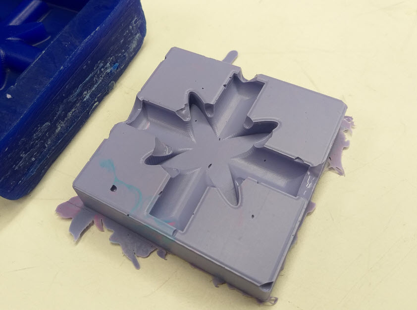
To begin with the individual assignment, the idea was to design a 3D mold around the stock and mill it. The dimension of the wax that we measured from our FAB lab was L:75mm W:145mm H:30mm. My Idea was to design a 3D Star shape. I started to design on Fusion 360 due to its ease with parameteric design and I was now used to it. I started my design with a simple Square of 55x55 mm required for my design to fit inside, then I draw another small rectangle to make a shell like structure where I will be able to build my design.
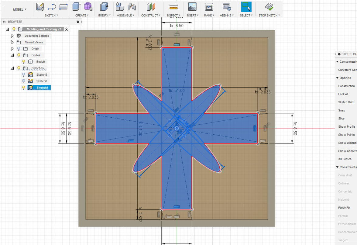
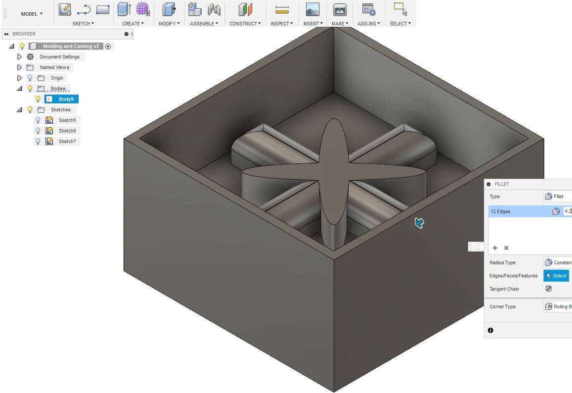
Then, I started to make a sketch of a plus symbol using a rectangle tool, and a multiplication symbol using Ellipse tool on top of each other inside the shell creating a star shape.
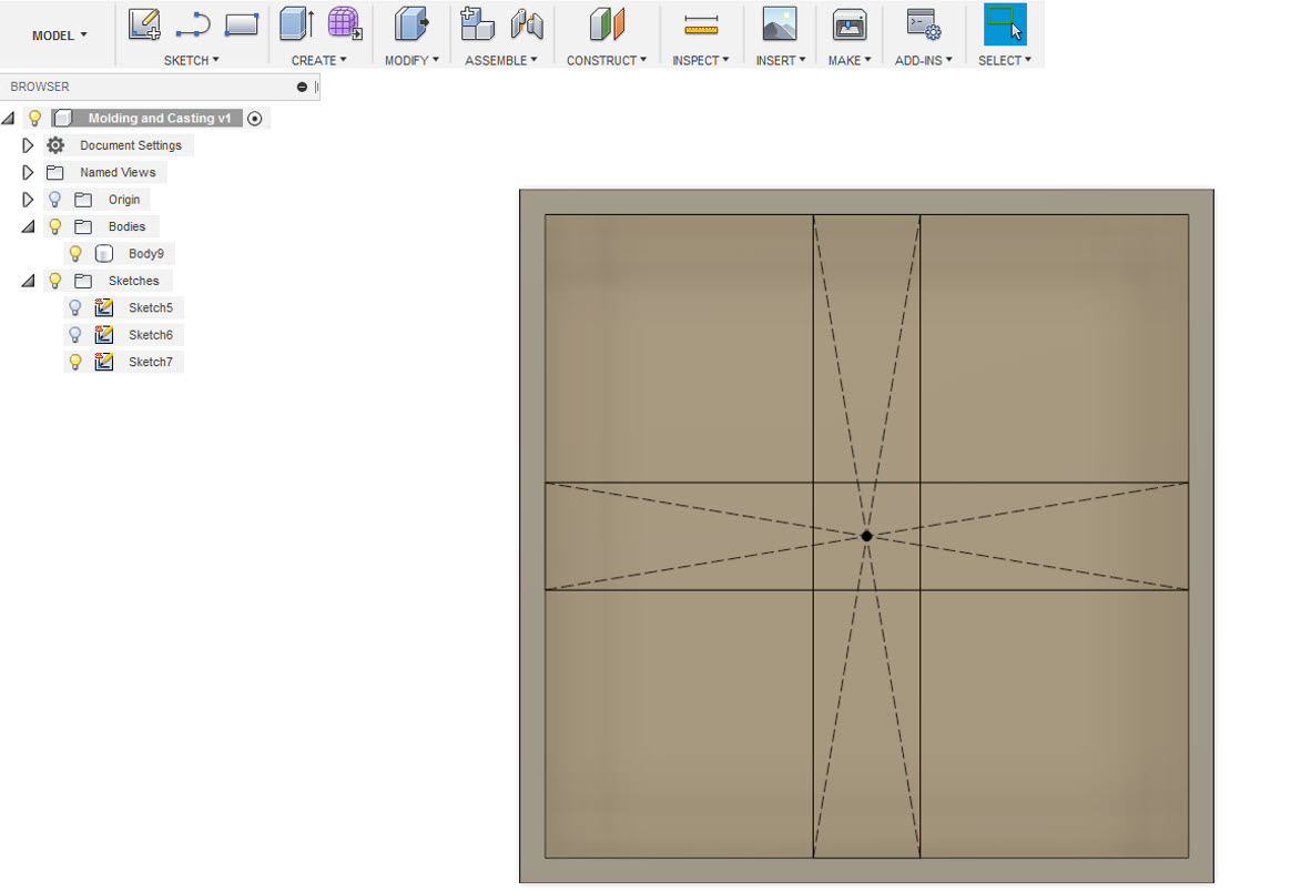
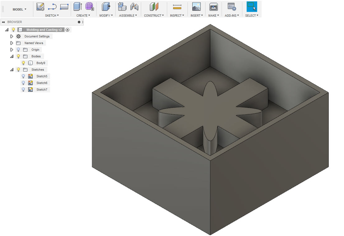
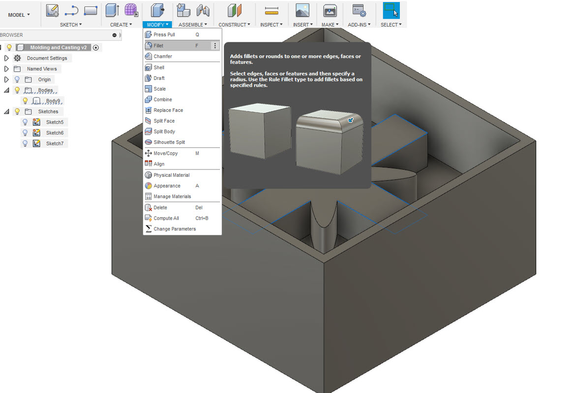
After drawing these sketches, I tried the shapes that needed to be extruded and I extruded the shapes to create a 3D Structure. The 3D Structure had sharp edges inorder to smoothen these Edges, I selected the edges which required smoothening then I utilized the Fillet tool to smoothen the Edges which thereby resulted in creating a Smooth 3D Shape inside the Shell.
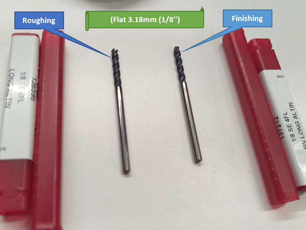
Then, I converted my design file to STL File, which is supported by the Roland SRM-20 Milling Machine to mill the wax mold. To mill the wax, I used 3.18mm flat milling for roughing and finishing. The Tool Path is generated in Modela Player 4 for roughing and finishing.
- Listed below are the steps to generate the Tool Path in Modela Player 4:
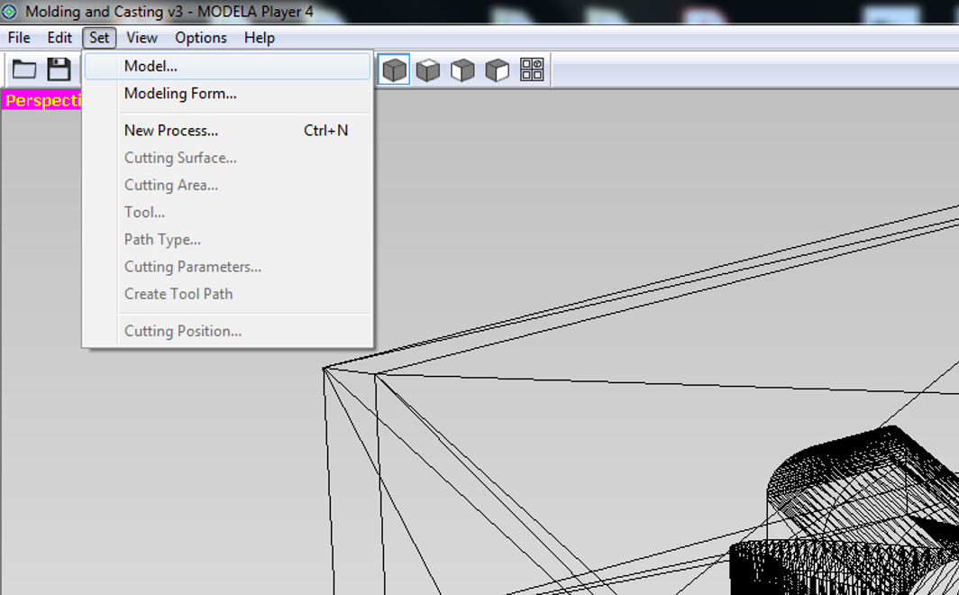
- Open the STL File in Modela Player 4
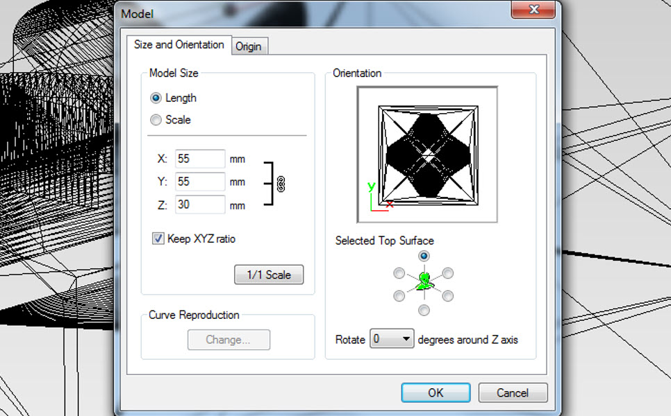
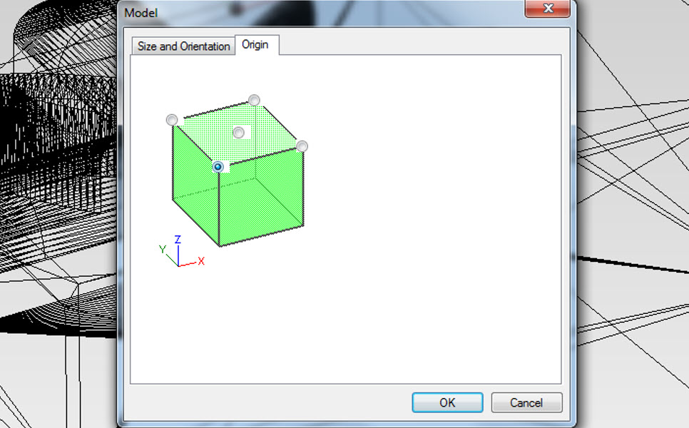
- Goto Set-->Model-->Size and Orientation, According to the size of the design I selected the Orieintation to Top
- Now for Origin setting Goto Origin, The top left corner shall be selected for origin
- The Toolpath for roughing and finishing is generated seperately, The Steps for Roughing are as follows:
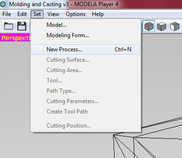
- Goto Set-->New Process
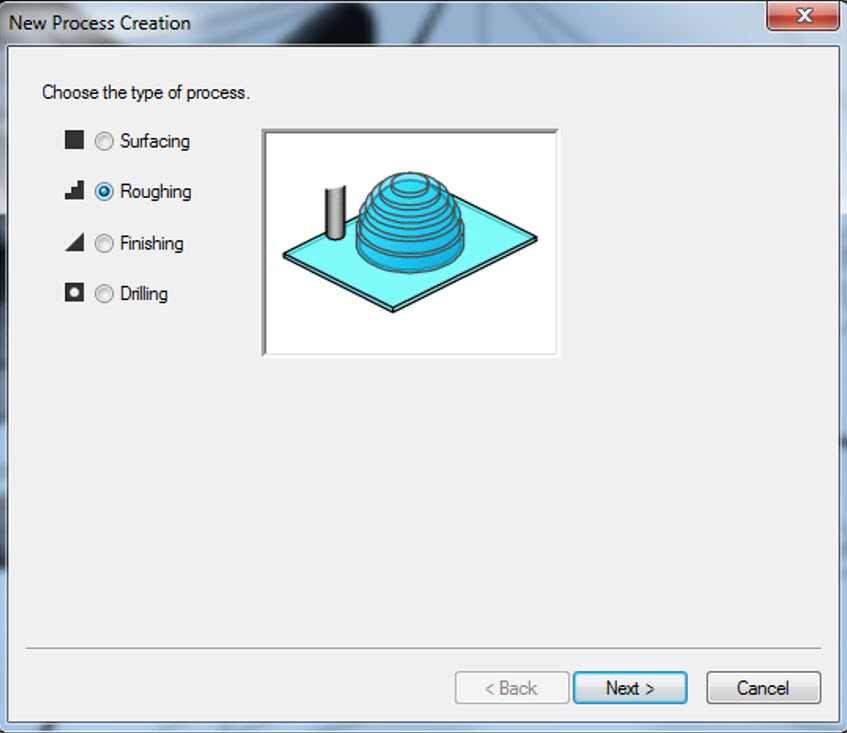
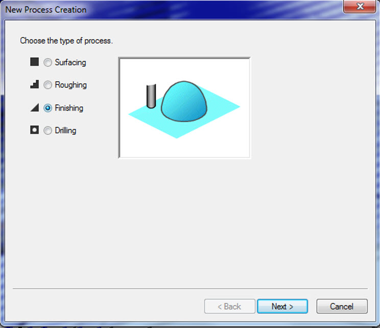
- In the New process creation, I selected the type of process to be roughing and press Next
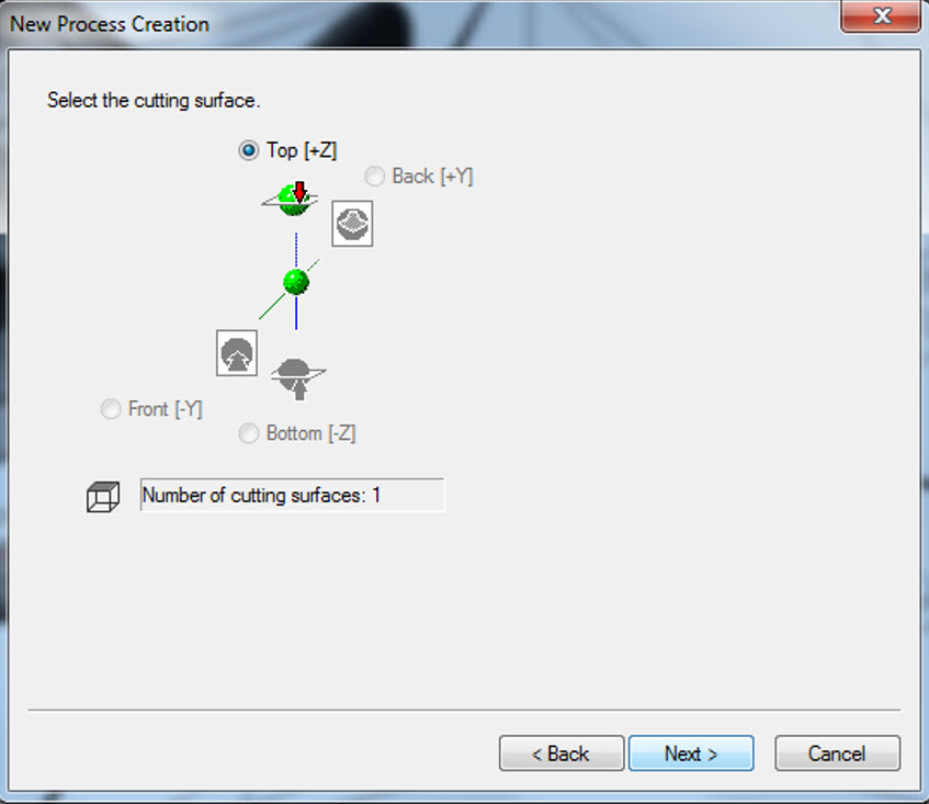
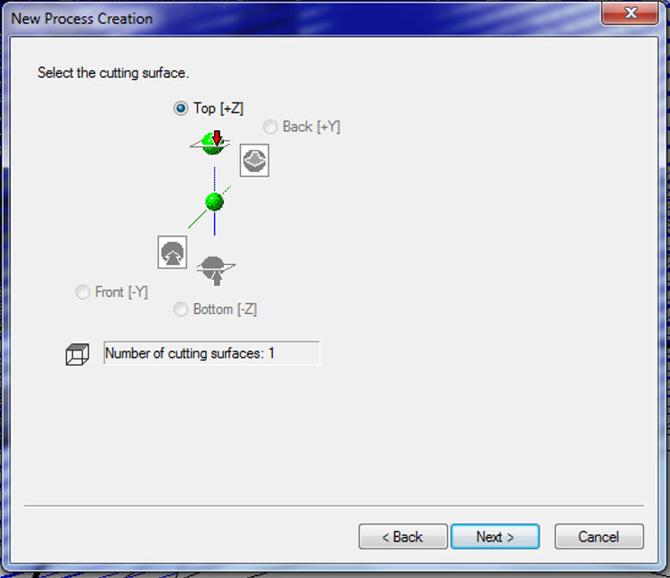
- Cutting surface is Top(+Z) and press Next
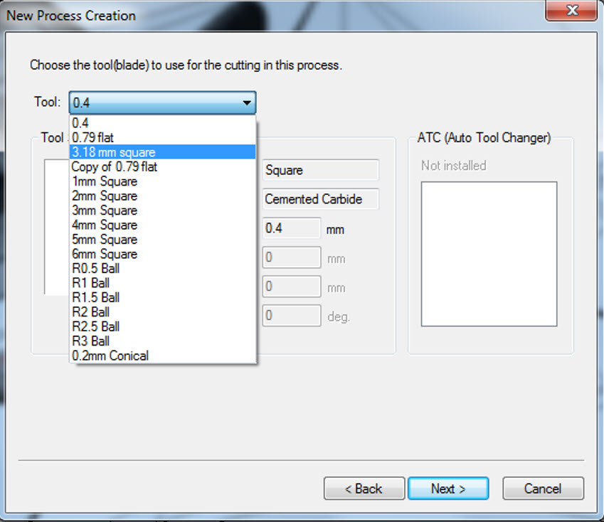
- The Tool used for cutting process is 3.18mm and press Next
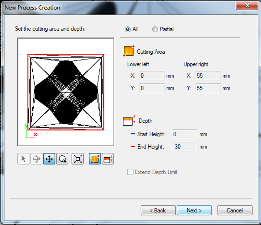
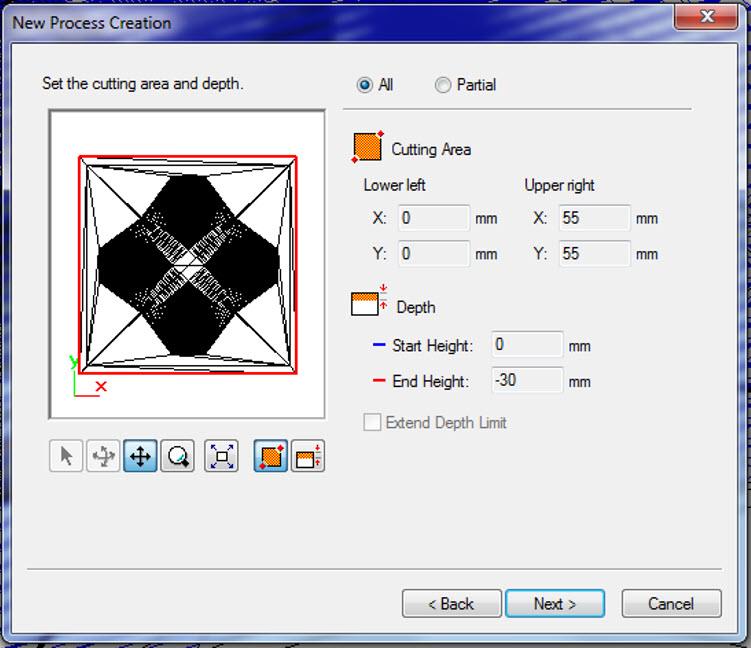
- The cutting area is automatically measured, no need to change anything, press Next
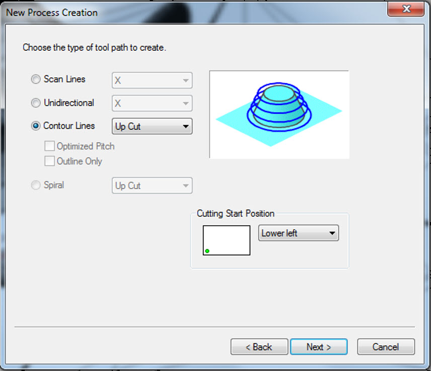
- The type of tool path to create is Coutour Line (Up cut) and the cutting start position is Lower Left, press Next.
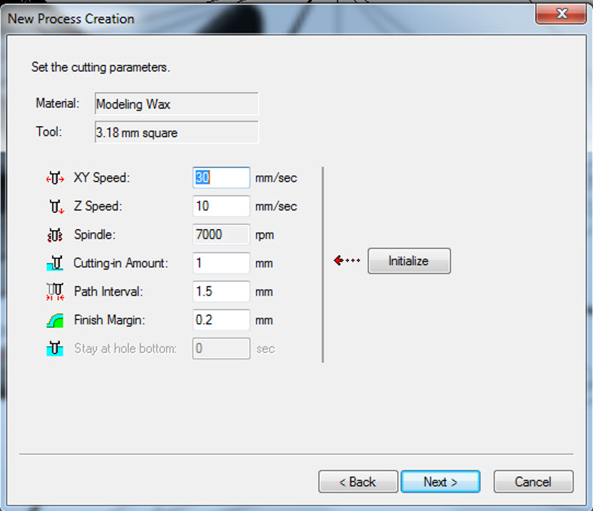
- The cutting parameters i.e XY Speed: 30 mm/sec, Z Speed: 10 mm/sec, Spindle: 7000 rpm, Cutting-in-Amount 1 mm, Path Interval: 1.5 mm and the finish margin: 0.2 are default values, no need to change, press Next.
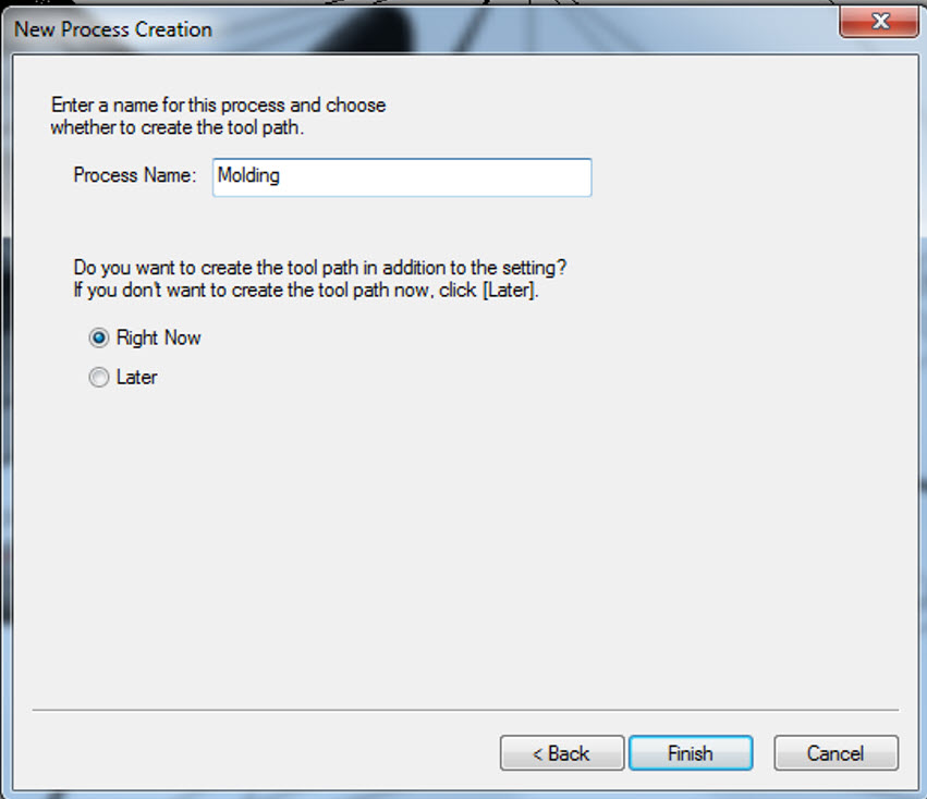
- Enter the Name of the Process and press Next
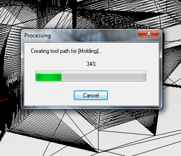
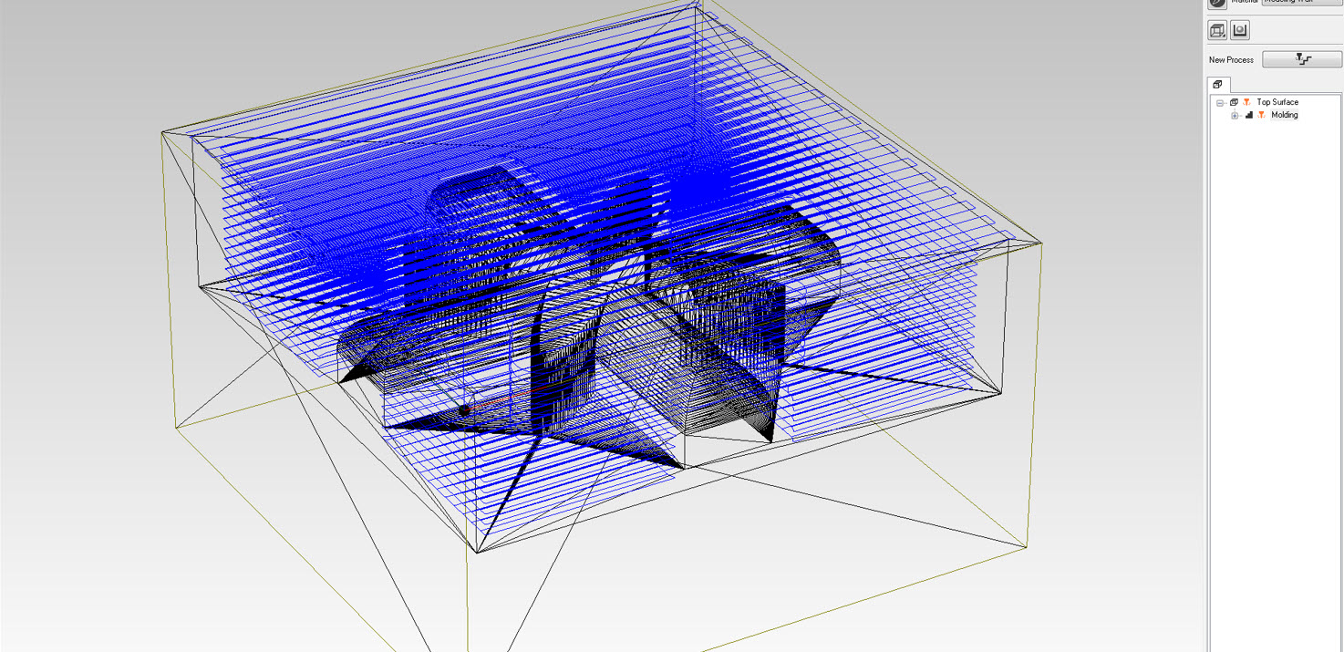
- The Tool path creation begin and the Tool path is being generated at the end
- The Steps for finishing are as follows:
- Again Goto Set-->New Process
- In the New process creation, I selected the type of process to be finishing and press Next
- Cutting surface is Top(+Z) and press Next
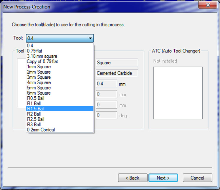
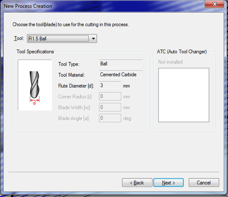
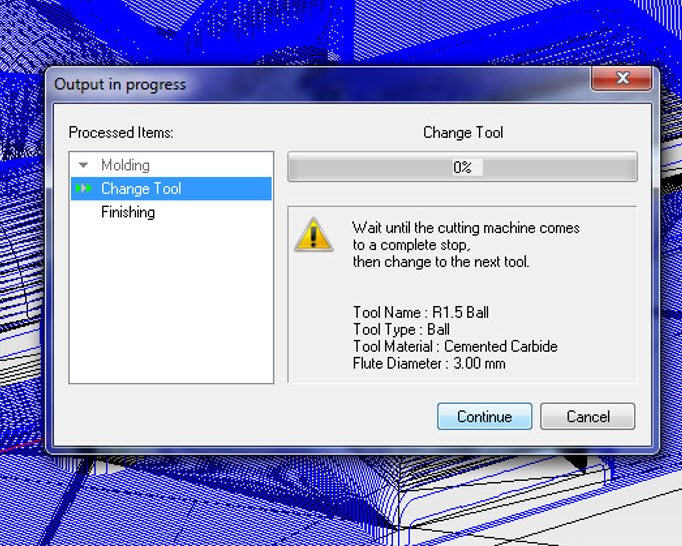
- The Tool used for cutting process is R1.5 Ball, the flute diameter is 3mm and press Next
- The cutting area is automatically measured, no need to change anything, press Next
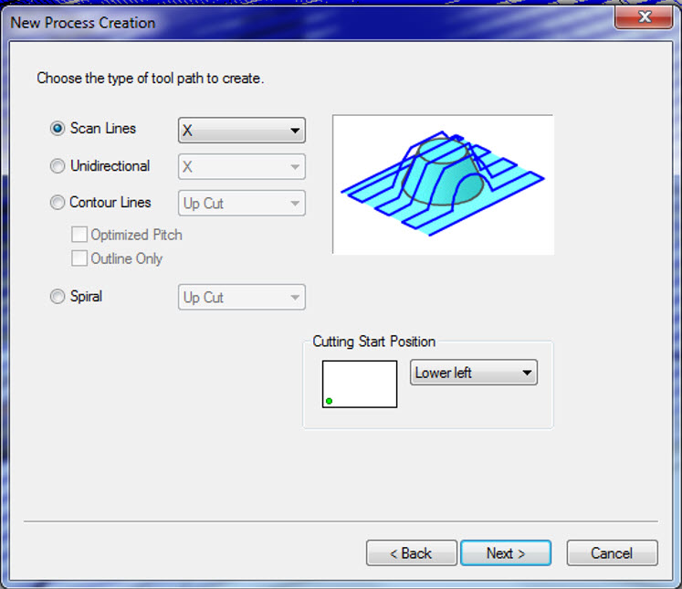
- The type of tool path to create is Scan Lines (X) and the cutting start position is Lower Left, press Next.
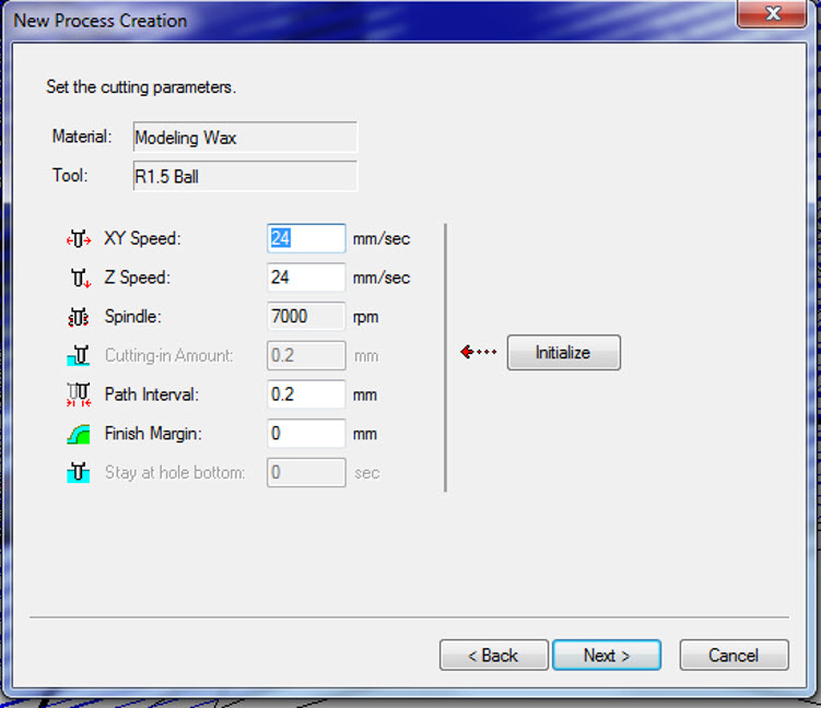
- The cutting parameters i.e XY Speed: 24 mm/sec, Z Speed: 24 mm/sec, Spindle: 7000 rpm, Path Interval: 0.2 mm and the finish margin: 0 are default values, no need to change, press Next.
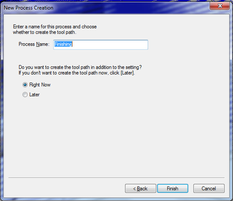
- Enter the Name of the Process and press Next
- The Tool path creation begins and the Tool path is being generated at the end
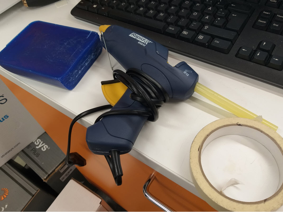
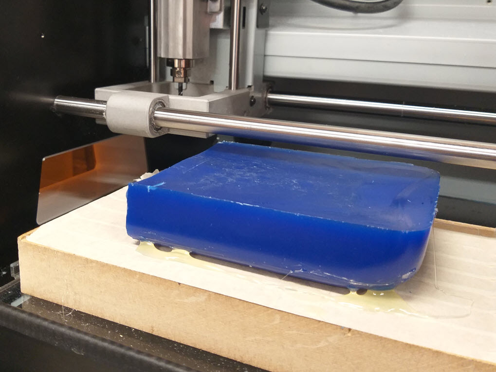
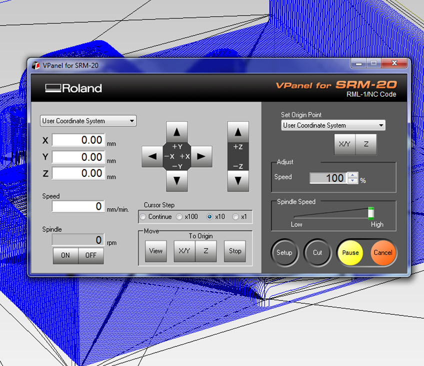
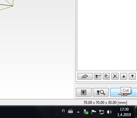
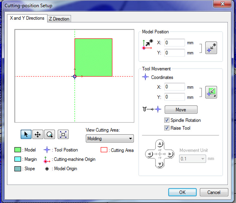
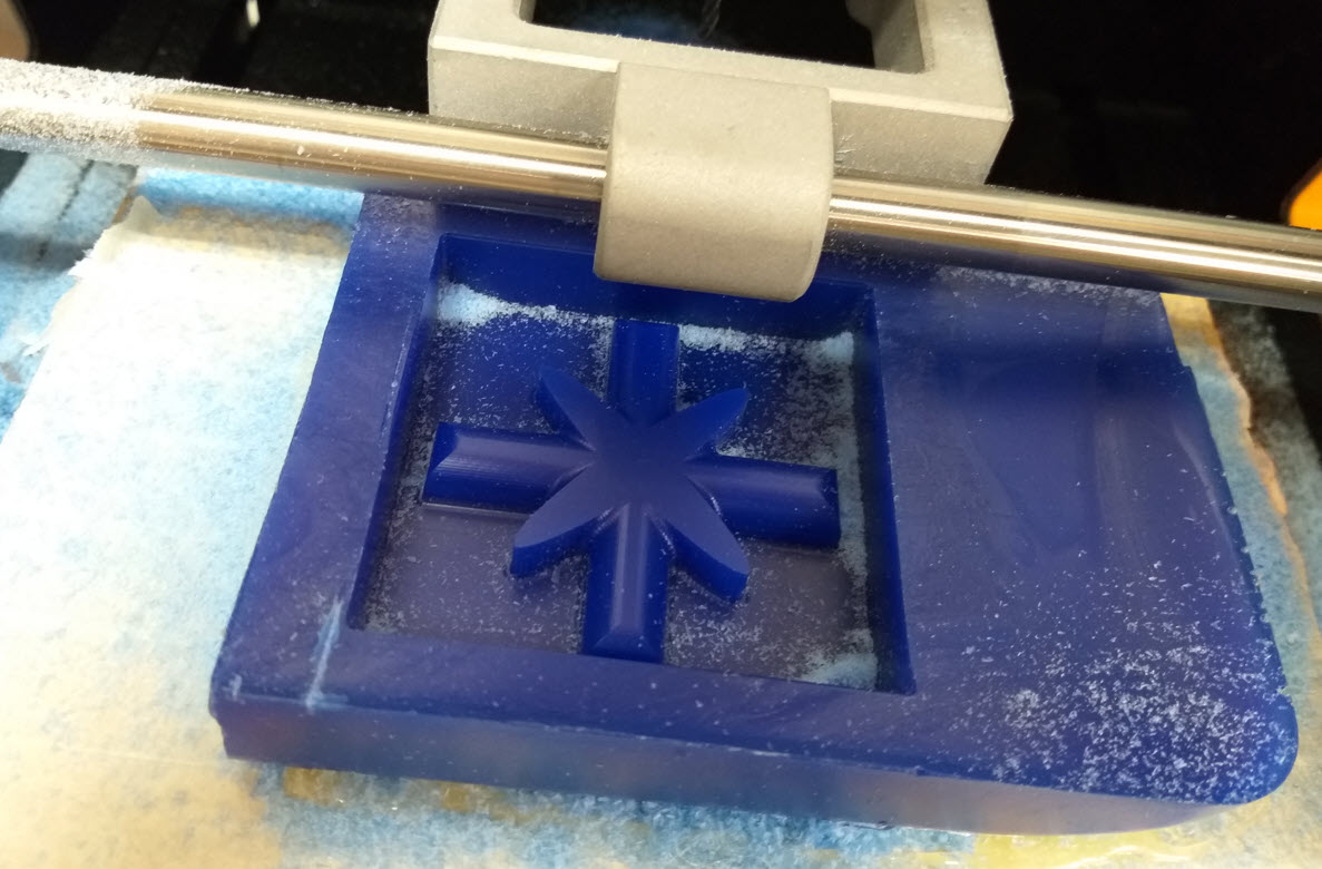
In the next step, I attached the wax block on the wooden base of the Roland Milling Machine. I used paper tape and silicone glue as adhesive to connect the block onto the wooden base. 3.18 mm Tool Bit was being connected, V panel window was used to do the origin settings. After doing the Origin settings, I went to Modela Player-4 and press the cut button on the lower right corner. A cutting position setup is being asked, I didn’t do any changes in that. Press Ok and the milling will begin. It is to be noted that the milling is done for roughening, after roughening is finished, there will be a pause and the Modela Player-4 will ask to the change the mill bit for finishing and it will begin the finishing.
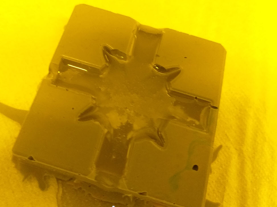
Now the wax mold is ready for OOMOO 30 casting. I started with the material preparation and casting of OOMOO 30 mold. The Materials process parameters are already discussed in the group work. Weighing, Mixing, De-airing, Mold casting, curing and then finally material casting.
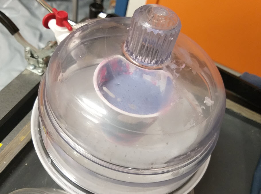
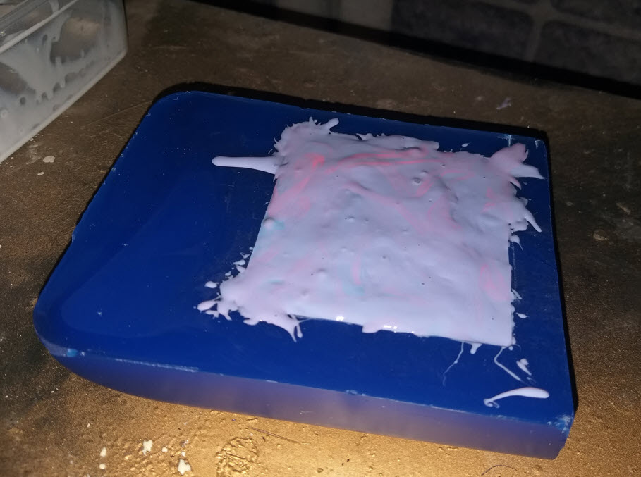
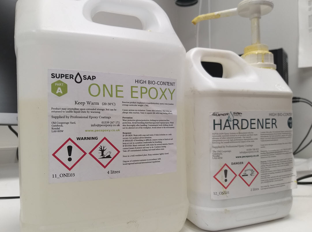
It can be seen that the trapped air in the OOMOO 30 mold resulted in not a good rubber mold, due to limited time, I couldn’t experiment with the smooth sil 940 for my design. I designed to move to the cast material that I will cast on OOMOO 30. I decided to use clear epoxy and hardener with a weight ratio of 25:5, pot time is 30 min and curing is 8 hrs.
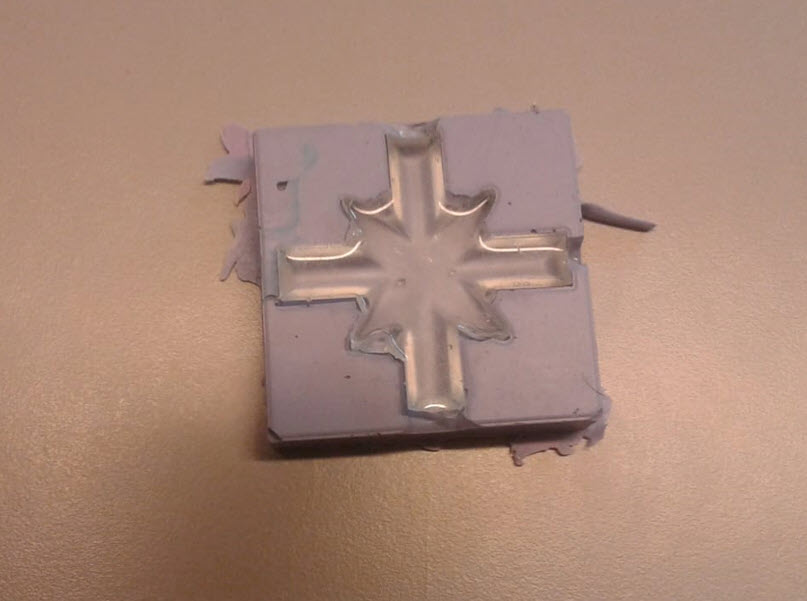
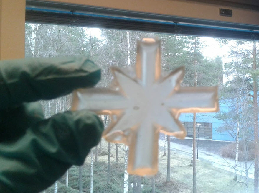
The result, came out to be pretty nice with the Epoxy. This week was quite lengthy and I learned a lot of things this week. Although the Rubber mold was not well still the Epoxy cast seemed pretty good.
Problems Faced
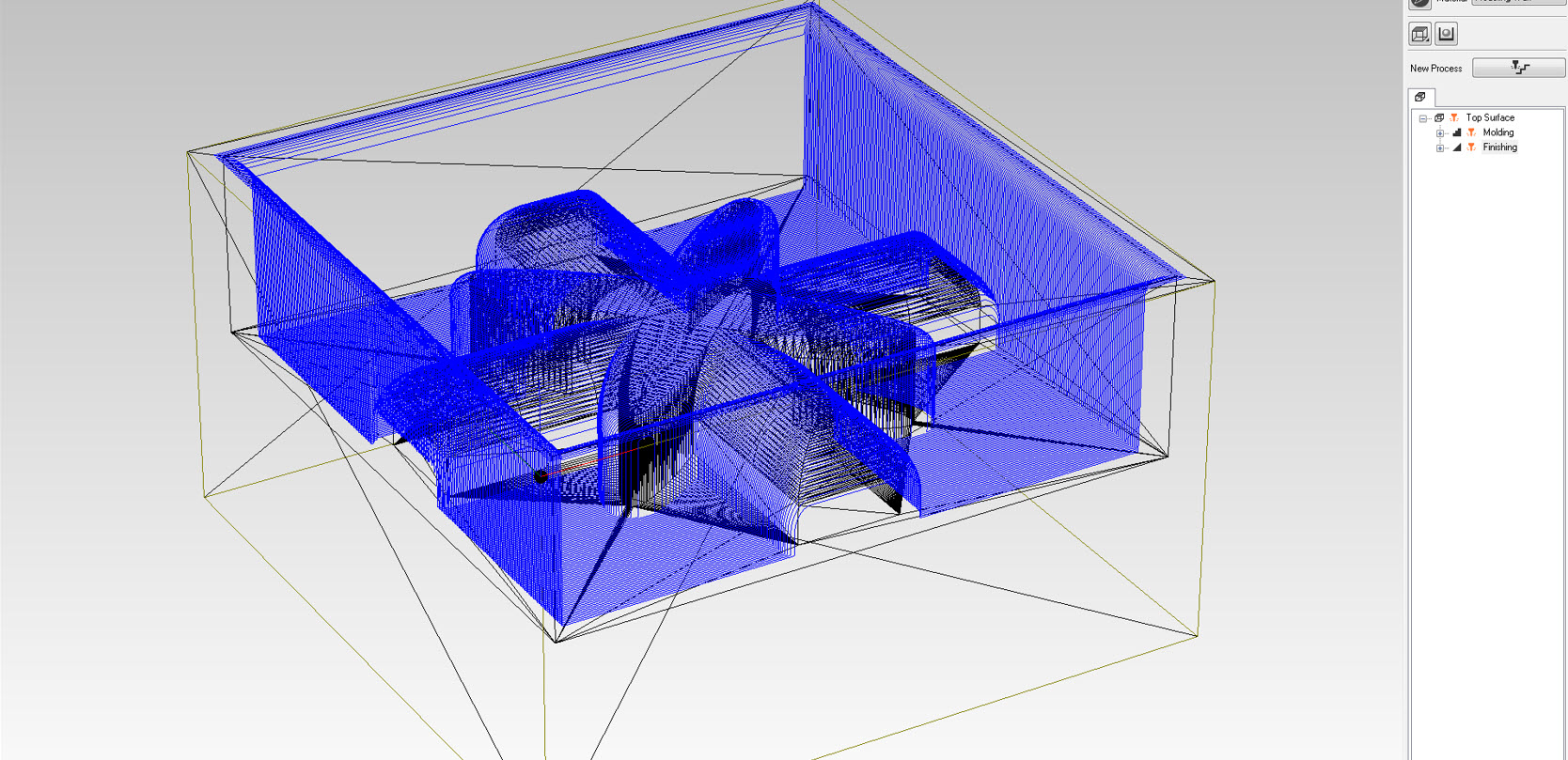
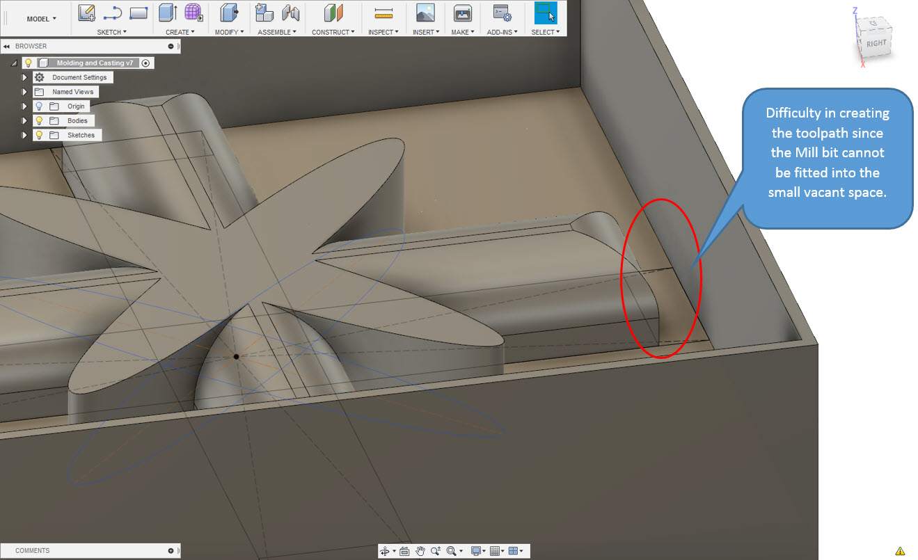
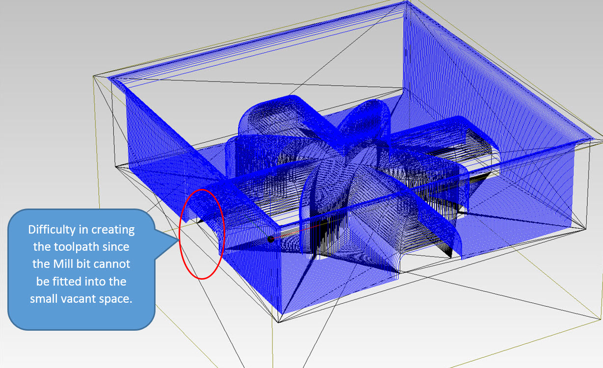
There was small problem that I faced during creating the toolpath in Modela, In the design at the edges, the toolpath was not created due to very small distance touching the outside block and the inner design. The distance have to large enough so that the Mill bit fits in, since I was unaware of this problem which I noticed later when the wax mold was being milled. Although the result of wax seemed to ok but the toolpath shall be deep as seen in the 3D model
Another Problem that I faced was the result of mold with OOMOO 30 was not of good quality and still after vaccum dissication, the bubbles still remain inside and created not a perfect mold. I would recommend to use smooth sil 940 due to long curing time and high quality result
Resources Utilized
- I utilized these resources for this task:
- Autodesk Fusion 360, for 3D Modelling
- Modela Player-4